A Nixie Thermostat
Nixie Tubes
For the uninitiated, the nixie tube was a numerical display technology used in scientific instruments and calculators in the 1960s and 70s, before seven segment LED displays were invented.
They have one great aesthetic advantage over most other display systems, in that the digits are not formed from combinations of straight line elements, and so can be properly curved giving a much more pleasant appearance.
Manufacture and commercial use of nixie tubes ceased a long time ago, but it still possible to obtain "new" tubes which have been stored in warehouses for many years, and enthusiasts continue to build them into various projects. Type "nixie clock" into Google to see examples, some of which are beautifully put together. |
|
The vast majority of the current use of nixies is to build digital clocks, and having robbed some tubes from a piece of scrap test equipment from work, I built one some time ago.
To be different for my second nixie project - the one shown here - I built a thermostat for controlling my central heating.
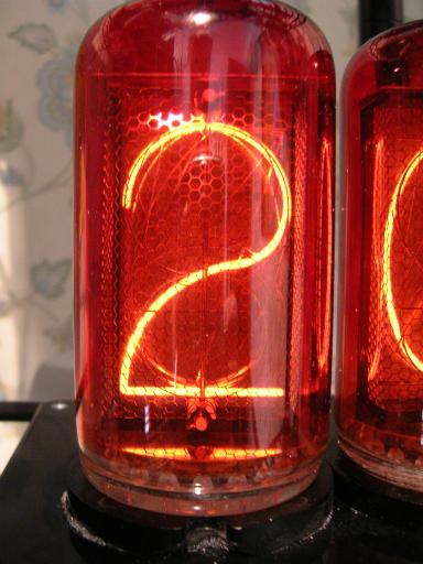
I obtained three Z568M tubes, unused and still in their original boxes.
I cannot find a manufacture date on the boxes or the tubes but I suspect the one year guarantee described - in German - on the box has probably expired.
These are the largest commonly available tubes, I think, and the thermostat can be easily read from across the room.
Some enthusiasts go the whole way, and control their nixies using valve technology from the same era, but I took the lazier approach and used modern components and a PIC microcontroller in my design.
|
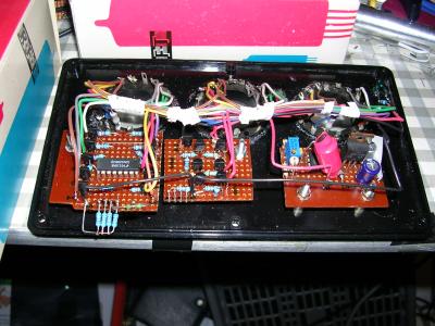
Here's the inside of the top panel, with three sockets for the tubes at the back and in front, from left to right, the cathode drivers and decoder, the anode drivers, and the high tension supply.
(Nixie tubes require a 200 volt supply)
Behind the panel you can see one of the original boxes that the tubes came in.
|
 |
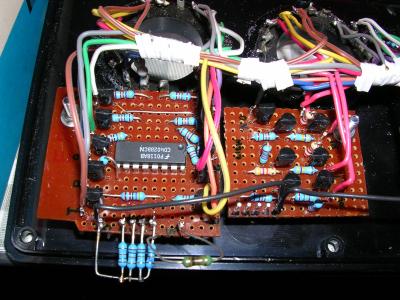
A close up of the cathode drivers (ten) and anode drivers(three).
(The 'extra' network of resistors at the bottom left provided pull-ups for the inputs during early testing without the controller connected.)
|
 |
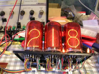
Under test on the bench. The controller is off to the left at the end of the ribbon cable.
|
 |
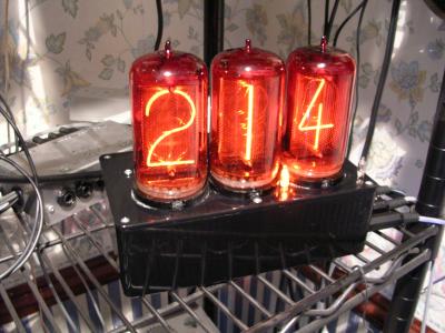
The completed thermostat in its box.
As you can see there's some room for improvement here, and the "decimal point" neon needs to be moved upwards a bit. The other neon on the right lights to indicate that the heating is running.
|
 |
Technical Description
For those who are interested, here's some more technical details on how this unit works:
Domestic Control System
The Nixie Thermostat is a small component of a server-based domestic control system which, in addition to controlling the central heating also switches lights on and off, and performs other functions.
The server communicates with a number of simple 'nodes' which receive inputs, for example from motion sensors, and provide outputs, for example activating the heating pump. Each of these nodes is based on a PIC microcontroller, and they communicate with the server using RS232 links, or by ethernet. All the control logic is in the server software, with only the minimum amount of logic in the nodes. You can find a lot more information about the system in my blog, here.
Thus, the Nixie Thermostat is not a thermostat at all, but simply a temperature measurement and display unit. It is the PC which makes the decision as to when to activate the heating, depending on time of day, and whether anyone is in the house.
Temperature Sensor
The temperature of the room is measured by a nifty little chip from Maxim, the MAX6576 which senses temperature and outputs a square wave whose period is proportional to the absolute temperature. It is easy for the PIC microcontroller to measure the length of a cycle of this square wave and so determine the temperature.
Control Board
The microcontroller is a 16F84. The only components necessary to make this operate are a pullup on the reset pin and a clock crystal, 18.432 MHz in this case. The cheaper option of using RC timing is not suitable for this application, as the clock frequency is used for timing the sensor signal and setting the RS232 baud rate.
Also on the controller board is a MAX202 RS232 level shifter, and a 78L05 regulator providing 5 volts for the logic.
Software
The microcontroller software has a number of duties to perform:
- Timing the waveform received from the sensor.
- Driving the multiplexed three digit display.
- Acting as a "UART" to receive and transmit RS232.
- Take the sensor reading and send it in a message to the PC, when the value has changed or when polled by the PC.
- Receive display messages from the PC and obey them.
- When communication with the PC is lost, cycle the display to activate all digits (Useful to test the wiring.)
The first three of these are time-critical and are all performed in parallel, based on a 19200 Hz timer interrupt generated by dividing the processor clock.
You will notice that the PIC does not have to do the difficult calculation to convert the sensor timing to a temperature in centigrade, this being performed by the PC software, which then sends a centigrade value back in a display message.
HT Supply
I decided that the whole unit should be driven from a 12v wall-wart so a chopper was needed to generate 200 volts for the nixies. I used a simple design based on an MC34063 chip, with an IFR740 doing the chopping.
Display Drivers
The multiplexed output from the PIC has four bits for the digit value 0..9, three bits to select which digit is lit, and one bit to control the "heating on" lamp.
The digit value is decoded by a CMOS 4028 and then ten MPSA42 transistors provide the drive for the cathodes.
The digit select signals each use an MPSA42 and an MPSA92 to provide the anode drive. I selected a 10k anode resistor which gives a satisfactory display brightness and (if I recall my calculations correctly) will keep the tube within or near its limits even if the multiplexing software were to fail and select one tube continuously. When there is nobody in the house, no digit select signals are active so the display is blanked.
One additional MPSA42 controls the "heating on" neon.
Design Notes
This was the first time I had used multiplexed drive for nixies, and I was a little concerned about ghosting and singing, but I took the lazy approach and did not bother with pull-middle resistors or software delays, knowing I could always add them if required. I was pleased to find that the display is totally silent and ghosting is only visible in a darkened room if you look very closely. Actually, on the bottom picture above you can just see a glow on the cross of the 4 in the tube displaying 2.
Due to a miscalculation, the first version of the software multiplexed at 37.5 Hz, which was far too slow and resulted in awful flicker. I tried 75 Hz but flicker was still discernable so I finished up doubling again to 150 Hz.